Not in Wellington, I know, and not about housing as I had promised, but this sad tale has got me intrigued. Multiple deaths and no doubt multi-million dollar lawsuits to come, but it is worth looking at in closer detail in case Wellington ever decides to go down the overpass route again. We used to have quite a few. Not so many now.
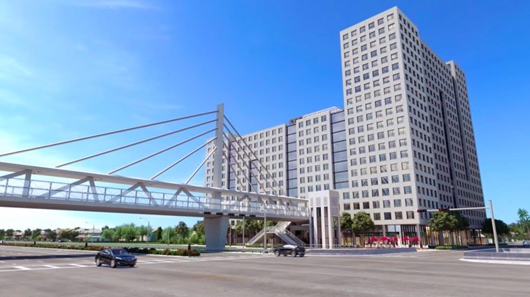
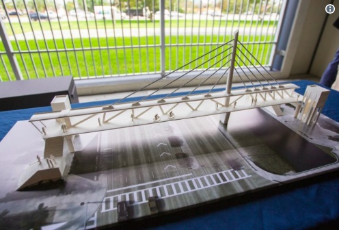
So, let’s recap a little first on what we know. FIGG Bridge Engineers design a bridge in Miami, near MIU, to have an off-centre tower and cable supports to a large concrete truss bridge over an extremely busy highway (didn’t want to cause congestion by closing the highway to traffic before? Well, I’m pretty sure it’s closed now…). They’ve designed hundreds of bridges before, so they’re not newbies to this game.
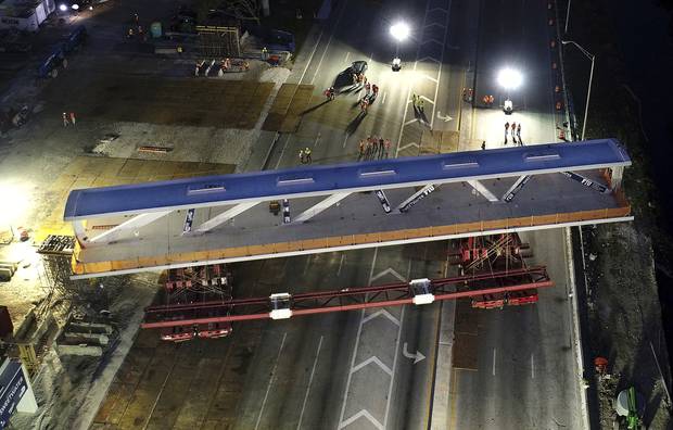
MCM (Munilla Construction Management) have built plenty of bridges before, but none quite went off the tracks like this one. They were employing a radical new method of construction whereby the entire truss / bridge on one side was wheeled into place overnight, and left propped on the two end supports – they hadn’t built the tower yet.
Now I’m no structural genius, but I see a problem right there. Stop me if I’m going too fast.
So, you have a bridge that is designed to have a tower, with cable stays to support the bridge. Not just one or two stays, but five cable stays to each side. But then you bring the bridge to site, carefully supported at two wide areas well in from the ends, and position it in place, spanning the eleven lanes of traffic. Maybe just ten lanes. But still: a lot of lanes. But you position it on the two support plinths, right at each end. And apparently, this stayed up like that for around a week. So you open the road up to traffic. Drive on through! Miami Times says they were doing some stress tests at the time.
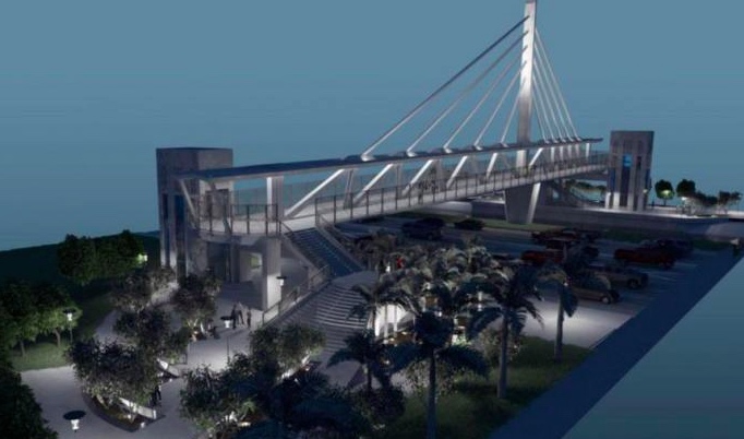
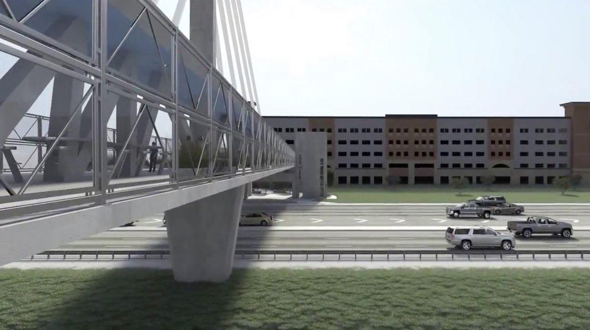
In other words, a bridge that is certainly looking like it was designed to be supported not just at the ends, but at five other places in between, is left supported at just the two ends. Clearly, the design has some structural redundancy built in – it is forming a truss, spanning ten lanes of traffic (or more), and evidently can do this without the five extra cables, or at least it can for a week.

But then it collapses, in a heap, on top of the workmen’s cars / trucks, and on top of the public driving by underneath too. Killing several. Maybe four. Maybe more. They can’t confirm the numbers of dead as they are squashed so flat under that 950 tons of concrete and steel. And evidently no-one thought that it was a problem to have the public driving under the construction site, erecting a cutting edge bridge construction, that is clearly not-so-adequately designed to span ten lanes of roadway for about a week.
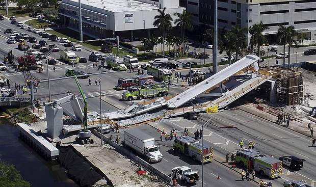
So here’s the thing I don’t get. If you are designing a bridge that is cable-stayed, then you need to have a tower to suspend those cables from. That’s a fairly basic sort of bridge-building 101 class right there, isn’t it? So, build that tower first, ready for hanging bridges from. Right?
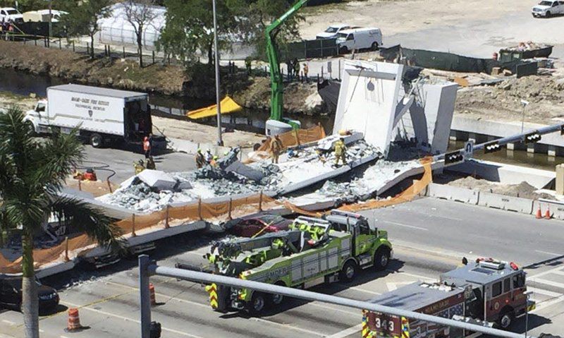
And if you are designing a bridge that is actually a truss, then you don’t need a tower, or cable-stays. You just need a truss for your bridge. So why have both? Does it mean that the cables aren’t really doing anything, except to look pretty? Surely not. Surely they are part of the truss as well?
The thing with a truss is that it works by having some members in tension and others in compression. And generally, you can’t swap those around. Everything is made into triangles, connected at the nodes, with compression members coming to a point, pushing together, and tension members pulling at that very same point.

And that’s the thing that stands out to me: if the cables are meant to be connecting to the points of tension, pulling up at those five points of load, that is putting all those truss members into tension, right? The top chord of the bridge is therefore going to be in compression, right? But here we have a bridge that is being supported, evidently, just at two extreme end points. Apparently, no temporary supports were in place. And that, my little Fishy friends, would seem to be another one of the problems right there: the bridge arrived supported firmly at two very broad intermediate areas as it was manoeuvred into place – but there doesn’t seem to have been any temporary propping. Surely, a propped area under every node, or even every second node, would seem to be the logical thing to do, until that central (non-existent) tower and its cables were in place? Surely?
But then again, I’m not a structural genius. These guys are.
Post-script: As Betterbee says below – only the long span had been put into place, not the other shorter span, that would be necessary to provide the counterbalance when suspended from the central tower (pylon is a better word, thanks). To get that central pylon working, it would have needed to be built pretty quickly – it’s probably back in the yard, waiting for it’s moment to be erected.



From the photos it appears that it wasn’t the whole bridge that had been put in place, only the longer span across the road – the artist’s impressions show another shorter span across a watercourse, with the unbuilt pylon between them.
Doesn’t change your point, though.
Comment from MCM website:
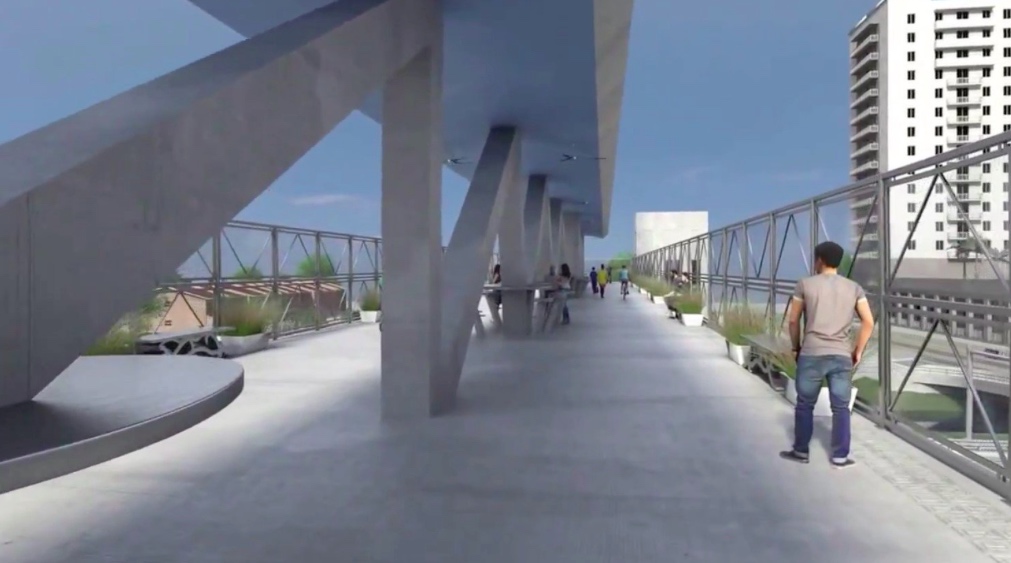
“This $9.3 million design-build project consists of the construction of a 320-long pre-cast concrete pedestrian bridge, sidewalks and plazas that will connect the City of Sweetwater with FIU’s Modesto A. Maidique Campus (MMC) over 8th street. The proposed MCM-FIGG bridge design includes a central support tower rising 108 feet above the road that will make the structure a landmark and a gateway for western Miami-Dade County. The bridge will feature:
A lighting system designed by Randy Burkett that will illuminate the bridge at night.
A 30-foot wide concrete canopy
Enough width to allow for the comfortable passage of bikes and pedestrians as well as a space for special events and student seating.”
http://www.mcm-us.com/projects/road-bridges/road-and-bridges-fiu-pedestrian-bridge
Where’s 60 MPa when you need them? ;D
“We need you 60mPa, you’re our only hope…!”
The mystery just gets deeper – and people like me, jumping in without knowing the full facts, don’t really help. Media reports are even worse though: take this report from Stuff today:
“US authorities say the cables supporting a pedestrian bridge under construction in Florida were being tightened following a “stress test” when the 950-ton concrete span collapsed over traffic, killing at least six people, injuring 10 others and flattening cars….. …As state and federal investigators worked to determine why the five-day-old span failed, Florida politicians pointed to the stress test and loosened cables as possible factors, and a police chief asked everyone not to jump to conclusions.”
https://www.stuff.co.nz/world/americas/102352344/us-bridge-collapse-victims-families-face-agonising-wait-builders-history-in-spotlight
Well, we know for a fact that the cables supporting the bridge from the pylon were not there, as there is / was no pylon. (There are, of course, horizontal cables as well, in the underside of the lower flange of the truss, for post-tensioning the wires.) There was a large mobile crane – visible in one of the photos above – but that won’t have been doing anything useful in terms of stressing cables.
I also watched a video last night of some backyard plonker in the USA tell the world on YouTube exactly why it collapsed – based on a picture of the bridge when it had already collapsed and was lying broken. I think that actually, what is needed is to watch the video, of exactly how and when the elements broke – was it a bay in the top chord of the truss? Or in the bottom chord? Or did the compression struts break through and punch out the other side under the immense pressure (if they didn’t do so before, they sure have now). See the second to last photo…
Some good facts on here, including links to the design drawings and philosophy.
The trussed sections were both designed to span without intermediate support from the cables, in the temporary and permanent cases. The tower and cables are ornamental
The connection between the cables (actually steel tubes) and top of the trusses are grossly undersized for providing any real support. At most, they’d assist with control of vibration when pedestrians walk over the bridge
http://happypontist.blogspot.co.nz/2018/03/the-collapse-of-fiu-sweetwater.html
Wayne – that’s a fantastic link, thank you so much. The Happy Pontist (a UK-based bridge designer) does indeed have a good discussion of the subject of collapse. What I think is amazing is that “the tower and cables are ornamental” – to me this is absolute madness. Something that is working so hard to look like a real structural diagram, turns out to just be a sham after all? Clearly not following an honest Modernist doctrine!
Commenters here seem to have covered all the major bases and yes support the damn thing, traffic is just temporary
The investigation will say what the problem was but the video shows it failing right where they were working so either someone did something monumentally stupid (entirely possible) or it was poorly designed and they were trying to patch it up somehow – either way wait for the official report
If you guys want a spooky story for bedtime then the cable-stayed lights over the Caketin had Reidbar style double female connections that could be turned by hand at time of construction by the guy who was doing the painting..
Probably rusted solid by now (cue evil laugh)
Remember folks, backpropping saves lives
https://www.osha.gov/doc/engineering/2003_10.html
Thanks 60 – much appreciated. Love the story about the Caketin.
Here’s the latest snippet from the Miami Herald – it may have been the changes requested by Department of Transport wot dunnit:
“Construction of the pedestrian bridge that collapsed and killed six people in the Miami area was behind schedule and millions over budget, in part because of a key change in the design and placement of one of its support towers.
Documents obtained by The Associated Press through a public-records request show that the Florida Department of Transportation in October 2016 ordered Florida International University and its contractors to move one of the bridge’s main support structures 11 feet (3 meters) north to the edge of a canal, widening the gap between the crossing’s end supports and requiring some new structural design.
The span’s signature, 109-foot-tall (33-meter-tall) pylon was to be built atop a footing, or base, at the northern end of the span. In addition to basic support, its design was also aimed at contributing to the aesthetics of the bridge, which itself was touted as an architectural marvel that would span a busy road and canal to connect the rapidly growing university to the nearby community of Sweetwater. In their winning 2015 proposal, designers said the bridge provided “spectacular views†for both pedestrians using the bridge and drivers passing beneath it. And they added that the tower could serve as a safety feature because it provided an “eagle-eyed location†for additional lighting and security cameras.
Videos of the collapse show that the concrete, prefabricated segment of the bridge started crumbling on the same end of the span where the tower redesign occurred, two days after an engineer on the project reported cracks in the same location. The segment that failed had been placed atop the pylon’s footing, and the taller tower section was to be installed later.
Though it is still unclear if the design change played a role in the failure, emails between the school, contractors, officials with the city of Sweetwater and permitting agencies show a project that ended up behind schedule, which had officials worried that further delays could jeopardize millions in federal Department of Transportation funds.”
http://www.miamitimesonline.com/news/key-design-change-stymied-bridge-cost-schedule/article_9bd569b6-2c80-11e8-b744-6319cca23a56.html